
Table of Contents
- Introduction
- Basics
- How it works
- Hardware
- Software
Introduction
About 5 years ago I purchased my first 3D printer. I had wanted one for years but couldn’t afford one until they came down in price to more consumer friendly rates. If you’re familiar with the technology then you know these devices kind of turn you into green lantern but just at really really, slow rate of speed. I love the implications they have to small scale prototype engineering. Before I would have to build my projects around or within the constructions of whatever project enclosure I had to work with.
Now you hop on whatever flavor of CAD software you prefer, grab your calipers and start mapping out the most wonderfully organized part. Custom fitted by design and printed at home. No sending away blueprints, paying a ton of money for custom parts or jamming wires into places they don’t fit.


With that being said after getting used to my little Ender 3 I started wanting more printers to decrease the production time of whatever I was making. Unfortunately for me I’m still a poor person so if I wanted more build surfaces I needed to improvise.
I started buying cheap broken printers on the internet. It wasn’t long before my office was filled with 3D printer parts and failed prints that were half beautiful, half string cheese. After refurbishing a few printers for other and making some designs that were more functional than laughable. I decided that I wanted a 3D scanner…..until I looked at the prices.


So I did what most people in my economic bracket do when they want something they can’t afford and looked for a cheaper open source version. After looking around at what was already out there I decided I could probably just make one of these on my own. After all most of them looked like glorified lazy-Susan’s. How hard could it be? Lol well after jumping down a neuro divergent rabbit hole. I became more interested in making my own scanners. Soon I found myself riding the dopamine levels into the sun and what started as pandemic project turned into an obsession’s to experiment and better understand the technology.
As I revised my designs I started running into a lot of the same problems others had scanning with their home made devices and cell phones. Outside interferences. Like lighting issues and the challenge of scanning things with reflective surfaces. Point clouds that needed tons of editing or were highly inaccurate. So I started looking at what made the more expensive scanners work so well and how I could revise my designs to work more accurately utilizing what I had at my disposal.
Fortunately for me there is a ton of research on this stuff by other people far more brilliant then myself and they have posted a ton of write-ups on how it works.
So I started with what I had laying around my house. By now I had not only been building scrapped together 3D printers for myself but for others as well and I had boxes of spare parts left over from upgraded machines and dissected throw away ones we used for harvesting parts (a local school gave a bunch of their students cheap delta kits as a project they got to keep. Most of them sold them at the end of the year for like $25 or less a piece on market place).Not great for printing with but filled with useful parts that can be repurposed on better machines.
How it works
Hardware
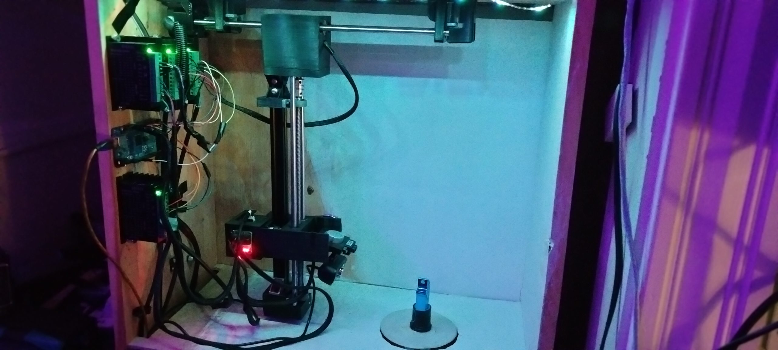
The scanner has 5 motors that control the platter, z-axis, y axis, tilt and pan functions. Each of the motors is hooked to a driver which all connect to Arduino Mega 2560. That board is program to respond to serial data which controls the signal sent to each of the motor’s drivers. Essentially it works the same as a 3D printer or CNC machine. In fact it was built with scrapped parts from both. One of the perks of being a tech for years is that I have an abundance of spare parts and recycled computers laying around. My plan is to switch to a custom board much like the ones you see in 3D printers. All driven with an embedded Mega 2560 and slots for the step drivers. Which in turn should be able to bring the over all cost down. I was originally going to design it run on a Pi but I purchased a couple before the prices started sky rocketing. My idea is for this to cost as little as possible so that everyone can have chance to prototype and modify it how they chose. So for now you can run it from most computers capable of handling 64 bit versions of Linux.
Software
Earl Grey
The scanner itself runs off a GUI based program called Earl Grey which I created primarily with python and Glade but incorporates and interacts with a number of devices and servers that utilize a variety of other programming languages and database interfaces. The notes on my Github will better explain and I also plan to a write up on my website for just the software itself. Again this has taken me the better part of 5 years to create. So now I’m trying to work out the final bugs and explain how it works. Sometimes I feel like programming and designing it was easier than trying to explain things to other people. Hopefully I’ll find other people who like my design, share my same passion for this technology and find it useful as a good stepping off point into prototyping their own fully automated 3D scanner.


It scans from multiple viewpoints and uploads the results remotely to any FTP host of your choosing. Currently it creates a pretty basic page to share the scans but I’m working to make it update a plugin for WordPress.

My plan is to eventually tap into the user hierarchy system of WordPress and allow it to help manage the scans between people online.
The scanner itself writes GPS meta information to each image via user stored data in the configuration section of the program. User’s can specify points for each one of the cameras viewpoints. I intend to work out a circle point algorithm for this that can use either steps taken from the stops on each axis points (or with a range finder) and feed it to stored meta data on each image. In theory I’m hoping this would allow for more acurate viewpoint mapping when processing my scans.
I am hoping within the next few weeks (no promises) I’ll finally be ready to upload all of my work to Github and some of the STL sharing sites. This has been a ton of work. More than I ever thought it would be. It’s taken literally years now for me to come up with a basic working prototype. To be honest I’m not even completely happy with it. I have learned so much in the process. I need to start some type of crowd funding though to buy some more parts and have some custom circuit boards printed that my at home mill just won’t be capable of doing.
My goal
My goal is to allow other people with a short amount of money to experiment with different 3D scanning technology.
Everything is open source I don’t care what anyone does with it. make Money give to your friends , have fun and make it your own, whatever. Just give me credit for my work.
I really just want a job and hoping this will prove to people I have more than a core knowledge about what I’m doing.
Below is a short video of my scanner running.